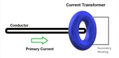
What is a Current Transformer?
As the name suggests, it is a type of transformer. Current transformers work on a similar principle to step-down transformers.
A current transformer (CT) converts the high-voltage current flowing through its primary winding (phase wire) into a low-voltage current flowing through its secondary winding (to the internal ammeter). The meter will then automatically be scaled or calibrated internally to display the original values.
For example, suppose the CT ratio is 1000:5 (in terms of current); Therefore, for the maximum primary current of 1000A, the secondary current will be 5A. Because it is also safe to monitor small currents in the circuit, not such large currents.
Such a large current can easily damage the measurement circuit. If you install an energy meter in the panel, then the three wires from the three current transformers (R, Y, and B) will converge in the meter; This makes it possible to display all three currents.

See image above. As you can see, the CT is mounted on a conductor that carries the main primary current. The output of the transformer is a secondary winding that winds around it, which converts the high current into a low current and then feeds it to the ammeter.
The meter used should also have the same ratio as the transformer. If the ratios don’t match, the readings will also show up as incorrect values. The direction in which the current starts to flow is called P1, and the output side is called P2. These terminals are marked on the transformer.
When mounting the transformer to the conductor, make sure that the P1 side is facing the input current and the P2 side is facing the output current. If the connection is incorrect, the value will not be displayed correctly.
The output of the transformer has two terminals – S1 and S2. Make sure to follow the terminals to connect it properly to the meter.
Don’t confuse how they work. It is very similar to a transformer. The conductor through which the current passes generates an electromagnetic field that excites the windings of the magnetic coil on the secondary side and induces an electric current in it.
The Ratio of the Current Transformer
Now let’s understand how CT ratios are interpreted and come into play. As mentioned earlier, a CT of 1000:5 means that a primary current of 1000A corresponds to a secondary current of 5A. The ratio of 1000:5 is 200:1.
That is to say, the current should be proportional in this range, according to the standard turns ratio formula of the transformer, TR=NP/NS=IS/IP; where TR is the number of turns ratio, NP is the number of primary windings, NS is the number of secondary windings, IS is the secondary current, and IP is the primary current.
By increasing the number of secondary windings, the number of NSs, the secondary current can be made much smaller than that in the primary circuit under test, because as the NS increases, the IS decreases proportionally.
In other words, the number of turns in the primary and secondary windings is inversely proportional to the current.
Key Points of Current Transformers
It is important to remember that the secondary winding must never remain open. This is because the load flowing out of the primary current should be evenly dissipated somewhere in the current transformer.
Therefore, it is necessary to set up the secondary windings. Therefore, if there is no path for the current to flow in the secondary winding, then there is no demagnetization flux due to the secondary current.
Since the secondary coil does not have a reverse ampere turn, the non-reversing primary EMF will produce an unusually high magnetic flux in the core. This magnetic flux creates core losses, which are subsequently heated and generate high voltages on the secondary terminals.
Since the voltage is so high, the insulation of the windings will break down. Then CT will be useless. Therefore, it is always necessary to maintain the secondary winding connection.
It’s important to note that the standard clamp meter you use to measure current is also a type of current transformer. You must have seen how to grip the windings of wires with pliers. It has the same concept as a current transformer. This is the concept of a current transformer.
